-
相较于陆上风电,海上风电具有资源丰富、风向稳定、风力强劲等优点[1],受到了新能源行业的重点关注。然而由于海洋功能区划等因素的影响,近海风能资源开发逐渐受到限制,海上风电逐渐走向深海化、远海化。
为适应海上风电深海、远海化这一改变,包含三桶导管架基础在内的新型基础应运而生。以三桶导管架为基础的海上风电机组的安装就位,往往需要自升式可移动平台进场施工。在桩靴插桩的过程中,挤土作用将直接影响邻近结构的稳定性,严重时邻近结构可能发生倾覆破坏;同时,挤土作用使得桩靴周围土体产生软化,影响邻近桶的在位承载特性。
前人针对桩靴贯入以及桶形基础承载特性等问题进行了大量研究。
针对桩靴贯入这一问题,Hossain等[2-3]利用离心试验和有限元分析,研究了黏土中土体的流动机制,并分析了土体空穴深度与土体强度的关系,提出了单层黏土中承载力的计算公式;Martin等[4]通过对黏土地基离心机实验和理论分析总结,提出了适用于在浅埋桩靴基础的地基失效模型。潘泽华等[5]利用CEL技术模拟了桩靴在常见海床地质条件的安装沉放过程,分析了沉放贯入机理的差别。Zhang等[6]利用大变形模拟了桩靴基础的贯入过程,并利用小变形技术模拟了桩靴基础在组合荷载下的承载能力。王凯等[7]结合室内模型试验和有限元法开展了砂土中桩靴贯入对自升式平台水平承载特性的研究。
针对桶形基础承载特性这一问题,Yun等[8]利用塑性上限法,分析了吸力桶在均质黏土以及非均质黏土中的水平极限承载力和弯矩极限承载力。肖忠[9]通过深埋式大圆筒的力学方程,提出了计算大圆筒承载力的极限平衡法。在Fu等[10]的有限元模型中,在土体遵循修正剑桥模型和Tresca屈服准则的基础上,分析了吸力桶在单向荷载作用下的破坏模式,研究了吸力桶各向承载力,并提出了预测承载力的新方法。Hung等[11]则利用有限元模型,模拟了吸力桶基础的组合承载力,提出了组合荷载作用下计算各向承载力的新公式。Mana等[12]通过离心试验研究了浅埋式桶形(埋深<0.5D)的竖向承载力,分析了桶土界面的影响。
而针对桩靴贯入对邻近结构的影响,前人则进行了一系列数值模拟和试验研究。Xie[13]利用PIV技术,通过一些小比尺模型试验分析了桩靴在黏土和上砂下黏土层贯入时的土体流动机制,指出在黏土中主导机制是局部剪切破坏,在上砂下黏土层中主导机制则是挤压破坏,并分析了多种因素对邻近桩桩身弯矩的影响。Tho等[14]对比分析了解耦方法和耦合方法在研究“桩靴 - 桩”结构这一问题时的适应性。Zhang等[15]通过离心试验研究了邻近桩的水平承载特性,并将强度衰减系数引入到了p-y曲线中。Fan等[16]基于改进的Poulos法,引入了Y乘数,研究了桩靴贯入对群桩基础p-y曲线的影响,并将结果与离心试验和数值分析进行了对比,证明了该方法的可行性。
然而前人的研究主要集中于桩靴插拔对邻近桩基的影响,鲜少有人研究对三桶导管架基础的影响。本文章通过大-小变形联合计算方法对桩靴插拔过程以及土体强度衰减影响下的三桶导管架基础的承载性能进行模拟评估[5,17]。本文章首先采用CEL技术,模拟了桩靴在均质和非均质黏土中桩靴贯入过程对邻近三桶导管架基础的影响机理;并基于大变形模拟结果,考虑插拔桩后的土体扰动,并通过将土体响应关联到小变形模型,研究插拔桩后土体软化对邻近桶承载特性的影响机制。
-
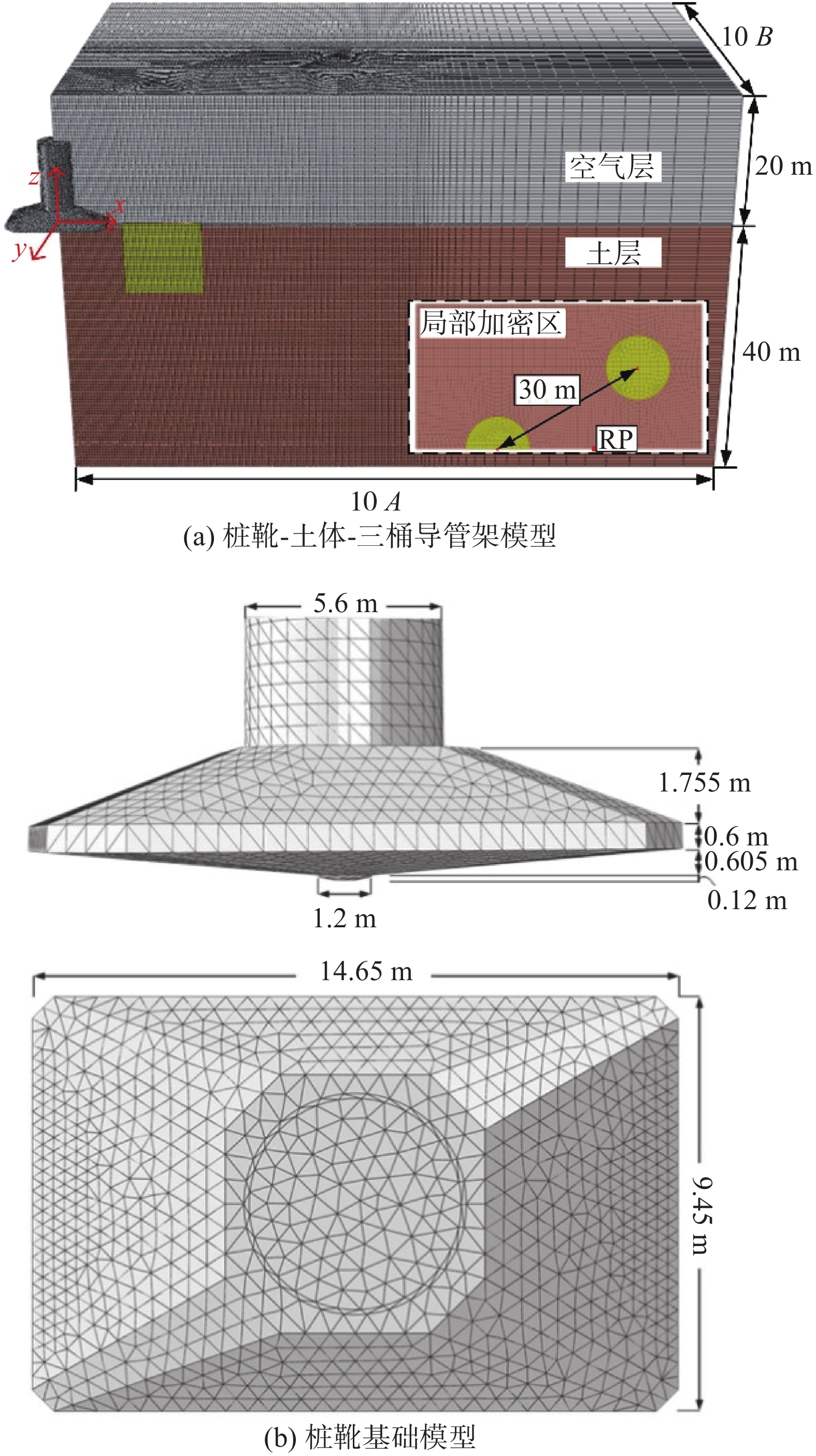
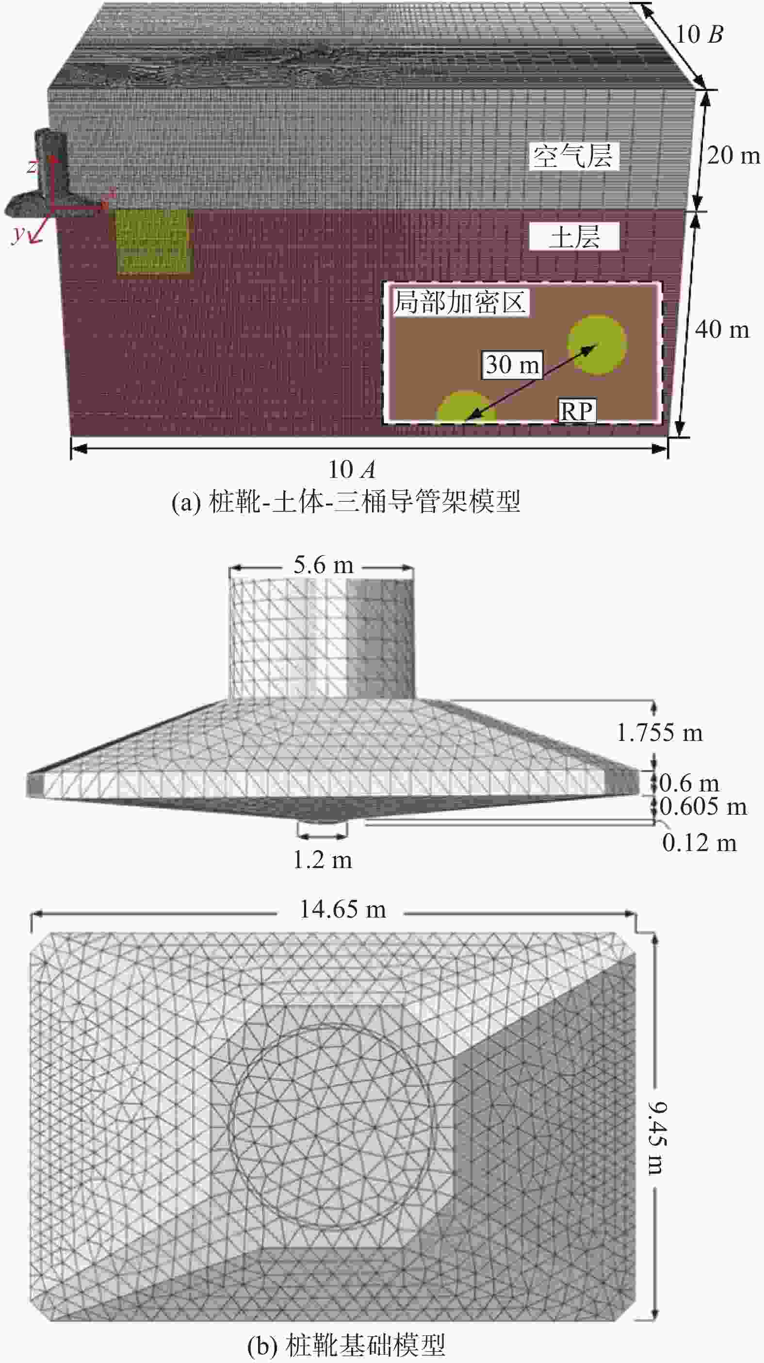
在本文中,类矩形桩靴基础最大截面尺寸为A×B =14.65 m×9.45 m,底部长轴倾角为159.5°,短轴倾角为148.7°。建模过程中,桩靴基础设置为刚体,最小网格尺寸取B/20[18]。
三桶导管架基础由三个薄壁吸力桶构成,正三角形分布,参考点RP位于正三角形形心处,与表层土体高度一致。其中,各吸力桶之间的形心距离为30 m;薄壁吸力桶壁厚t = 0.045 m;直径D = 11.8 m;埋深为10.8 m;泥面高度为0.5 m。在建模过程中,为提高计算精度,仅建立1/2模型,并将薄壁吸力桶等效为实体桶,并设置为刚体,同样的,网格尺寸取B/20[18]。
本文中土体强度分布如表1所示。
表 1 土层材料特性
Table 1. Soil properties
土体 性质 su0/kPa γ/(kN·m−3) Soil#1 均质黏土 20 6 Soil#2 非均质黏土 1+z 6 为准确模拟土体材料的非线性关系,黏土采用NGI – ADP土体模型,以考虑土体的非线性变形响应,其非线性应力应变关系如式(1)所示:
$$ {\gamma }^{{\mathrm{t}}}={\gamma }^{{\mathrm{e}}}+{\gamma }^{{\mathrm{p}}}=\dfrac{\dfrac{\tau }{{s}_{{\mathrm{u}}0}}}{\dfrac{{G}_{\text{max}}}{{s}_{{\mathrm{u}}0}}}+{\gamma }^{{\mathrm{p}}} $$ (1) 式中:
γ t ——土体剪应变(无量纲);
γ e ——弹性剪应变(无量纲);
γ p ——塑性剪应变(无量纲);
Gmax/su0 ——剪切模量刚度,本研究中取为定值,Gmax/su0= 250(无量纲);
τ/su0 ——当前剪应力与土体抗剪强度的比值,由式(2)决定(无量纲):
$$ \dfrac{\tau }{{s}_{{\mathrm{u}}0}}=2\dfrac{\sqrt{\dfrac{{\gamma }^{{\mathrm{p}}}}{{\gamma }_{f}^{{\mathrm{p}}}}}}{1+\dfrac{{\gamma }^{{\mathrm{p}}}}{{\mathrm{\gamma }}_{f}^{\mathrm{p}}}} $$ (2) 式中:
γ p ——土体当前塑性剪应变(无量纲);
$ {\gamma }_{f}^{{\mathrm{p}}} $ ——土体破坏时塑性剪应变,本研究中取为定值,${\gamma }_{f}^{{\mathrm{p}}} $= 0.2(无量纲)。
考虑到大变形计算十分耗时,而本文所涉及的模型具有对称性,因此土体仅建立1/4模型。在建模过程中,土体采用欧拉域建模,为确保土体能够在区域内流通,避免边界效应的影响,空气层厚度为20 m,土体厚度为40 m,土体长轴向长度为10A,短轴向宽度为10B。并对桩靴和三桶导管架基础周围土体进行局部加密,加密区域为3A×3B,加密尺寸取B/20[18]。
“桩靴-土体-三桶导管架系统”之间的位置关系由桩靴边缘与吸力桶边缘之间的距离,即净间距L决定,本节以L/B = 0.2工况为例进行建模,装配后具体模型如图1所示。
在模型中,接触行为有:(1)桩靴基础与土体之间的接触行为设置为光滑接触;(2)吸力桶与土体之间的接触行为设置为罚接触,摩擦系数取0.6,并允许接触后分离。
在模型中,约束行为有:(1)对土体各对称面设置相应的速度约束,并将各侧面和底面固定;(2)对三桶导管架基础的参考点施加沿y向的对称约束,即y向的速度和转角约束为0; (3)对桩靴基础贯入速度取0.2 m/s[19]。
-
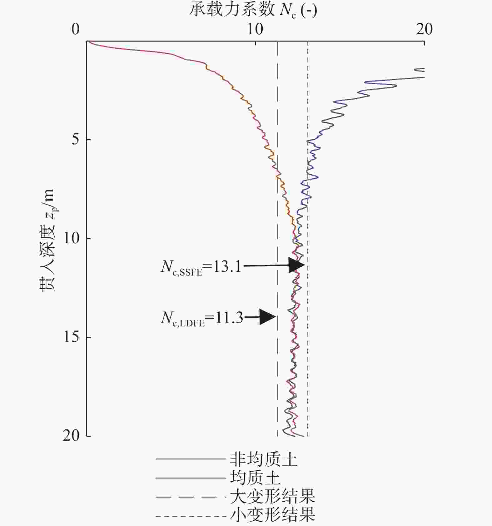
前人[20]研究结果表明,CEL大变形技术对解决桩靴基础贯入这一问题具有极好的实用性。在本文中,为验证本文所取的最小网格尺寸1/20B和贯入深度0.2 m/s的准确性,使用本文所涉及的土体材料,计算最终的承载力系数Nc,并与Hossain[21]的结果进行对比,计算结果如图2所示。
本文通过CEL技术在均质黏土和非均质黏土中模拟得到的桩靴贯入承载力系数最终均收敛于12.5,介于11.3 ~ 13.1。本文所取的贯入速度和网格尺寸满足要求。
-
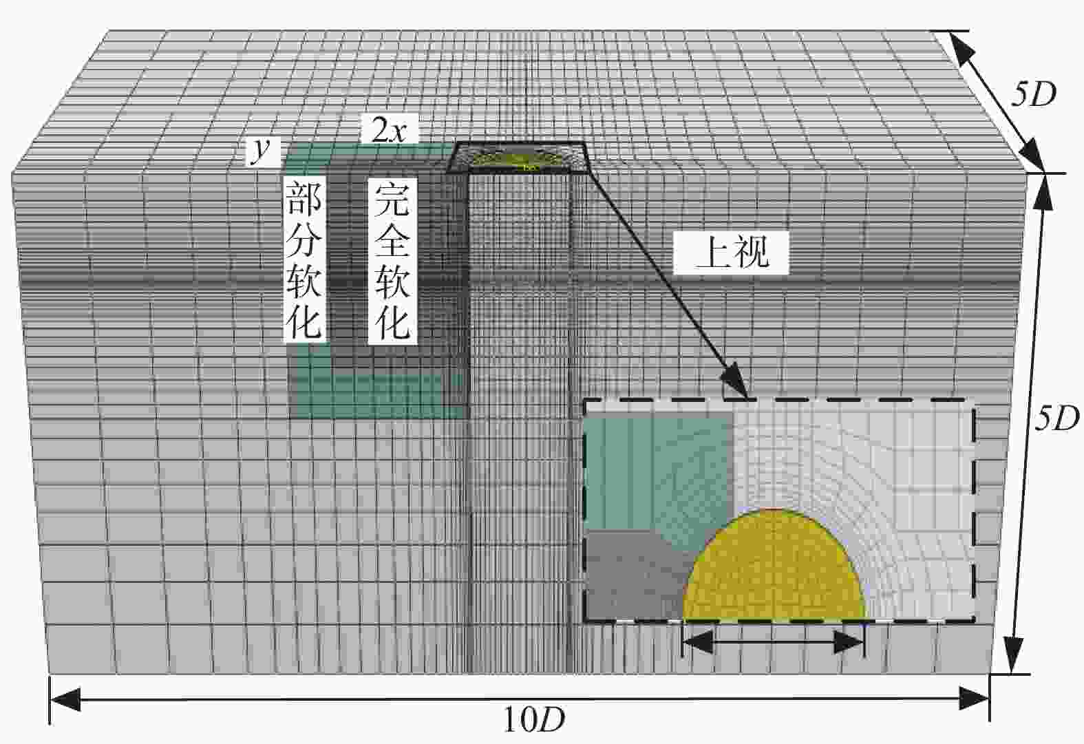
由于在本文中,涉及到土体软化工况和无软化工况,相较于无软化工况,软化工况要对划分出相应的完全软化区域(桩靴足迹)和部分软化区域(桩靴足迹周围土体),因此其网格划分情况更为复杂。本文以soil#1中L/B = 0.2工况为例,介绍本文所涉及的小变形模型。
如图3所示在小变形模型中,根据模型对称性,建立1/2模型,参考点位于泥面高度处。其中,吸力桶基础为薄壁桶,不进行抗弯刚度等效,设置为弹性体。土体最大范围为5D×5D×10D,沿邻近桶桶壁和桶底处,最小网格尺寸取0.02D[22],并划分出相应的完全和部分软化区域,其具体范围须由大变形模拟结果确定,详细描述见章节3部分。
-
Liu等[23]将参考点设置到桶底高度处,模拟了长径比为0.5的吸力桶在均质黏土中的各向单轴承载力系数。本节依据文献的设置,进行了模拟。结果如表2所示,模型结果与文献的最大误差仅为7.85%。
表 2 小变形验证结果
Table 2. Validation results of small deformation
文献 承载力系数 水平向/NcH 弯矩向/NcM 竖向/NcV Liu等[23] 4.50 1.63 10.75 本模型 4.37 1.51 10.55 误差/% 2.90 7.85 1.90 -
当桩靴基础与邻近结构之间的距离介于一定范围内时,分析其对邻近结构影响是不可避免的。根据SNAME[24]的规定,在1倍的桩靴直径内,必须分析桩靴贯入对邻近结构的影响。因此,本文分析L/B = 0.2到L/B = 1范围内(间隔L/B = 0.2)的影响机理,以及桩靴贯入导致的转角位移。根据要求,海上风电机组在从安装到退役这一过程中,其最大转角不应超过0.5°,其中桩靴贯入过程中机组基础转角一般不应超过0.25°(~0.004 4 rad)。
在本文中,为确保桩靴贯入一定深度时基础转角位移量达到稳定,最大贯入深度zp = 20 m。并依据邻近桶底部的速度矢量方向,将其分为两个阶段,其中浅层贯入阶段速度矢量方向斜向下;深层贯入阶段速度矢量方向斜向上。
-
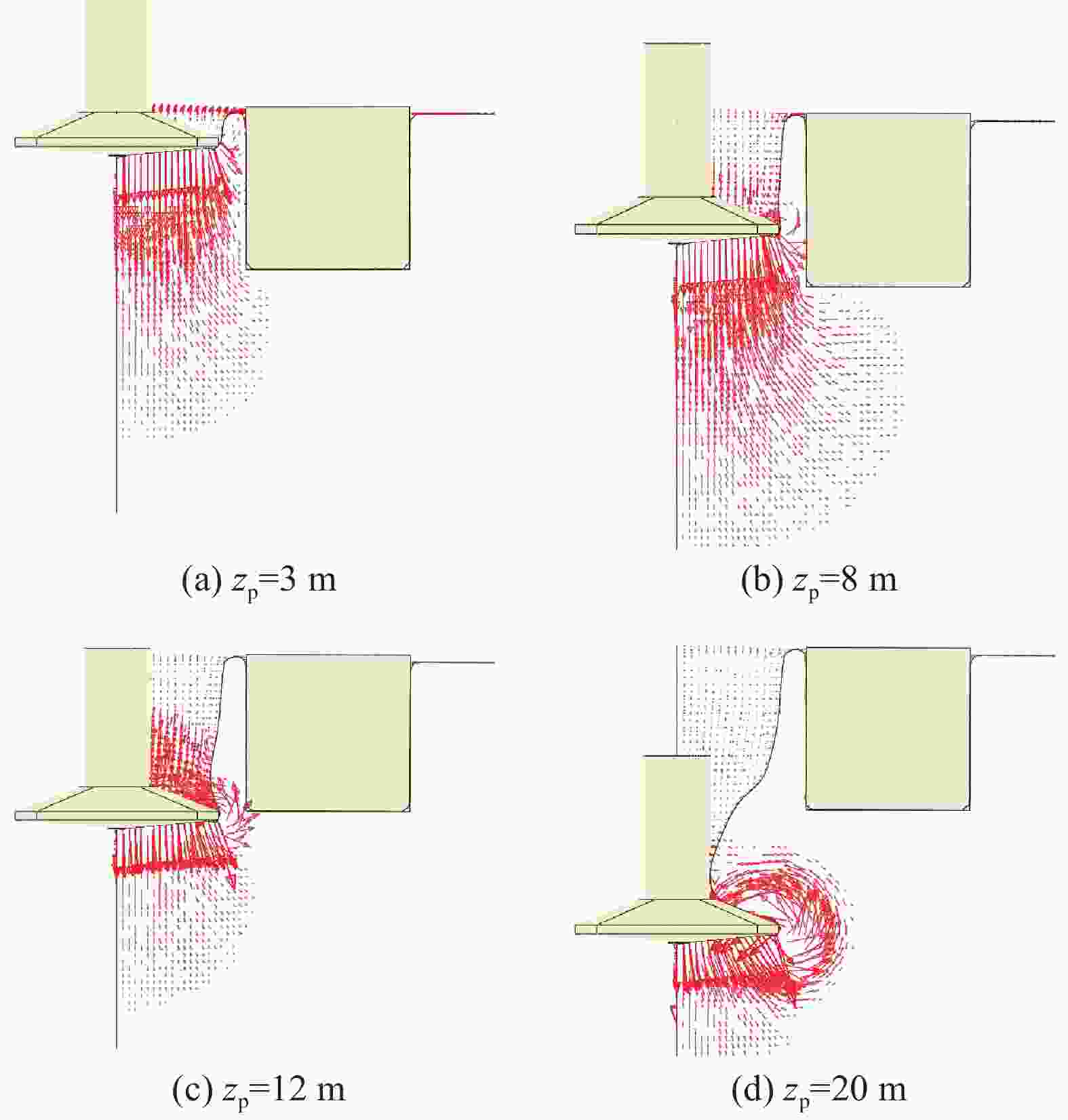
图4展示了在soil#1(均质黏土)中L/B = 0.2工况中的桩靴贯入过程周围土体速度矢量图,为方便界定贯入过程的土体流动机理的演变规律,在本工况中,选取贯入深度zp = 8 m为界分为了两个典型贯入阶段进行分析。
在浅层贯入阶段中:图4(a)显示,0 – 3 m段,在整体剪切破坏作用下,桶壁附近的土体的流动方向以斜向下流动为主,斜上方的土体流动为辅,这将导致桶壁周围产生水平向右的推力和竖向向下的摩擦力以及弯矩。图4(b)显示,3 – 8 m段,贯入深度增加,空穴逐渐增加,局部剪切破坏逐渐形成。
在深层贯入阶段中:图4(c)显示,局部剪切破坏的形成将导致空穴土体回流,并在邻近桶桶壁产生抬升力。之后,随着贯入深度zp增加,桩靴上部空穴由回流土体填充,不再对导管架产生影响,如图4(d)所示。需要指出的是,针对L/B = 0.4至1的工况,土体流动基本一致,不再进行赘述。
图5展示了在不同L/B工况下的转角位移图。以L/B = 0.2工况为例,在土体流动的影响下,0 – 3 m段,导管架的逆时针转动逐渐增加;在3 – 8 m段,逆时针转动逐渐变为顺时针转动,当贯入深度增加到12 m时,转动位移不再发生改变。图中显示,在不同L/B工况下,随着L/B逐渐减小,转角位移逐渐减小,且在贯入深度<桶底深度段,不同L/B工况中的转角差值更为明显;同时,由于转动方向发生改变,且L/B越小,位移量越大,因此不同间距下转角位移会交汇于一点,即桶深位置处;之后,当桩靴贯入深度>桶底深度时,在L/B = 0.4至1的工况中,贯入深度达到桶深位置处几乎保持稳定,转角位移大小基本保持一致,而L/B = 0.2工况由于距离较近,此时仍对三桶导管架基础有所影响,因此和其他工况的位移会产生了一定的差值。
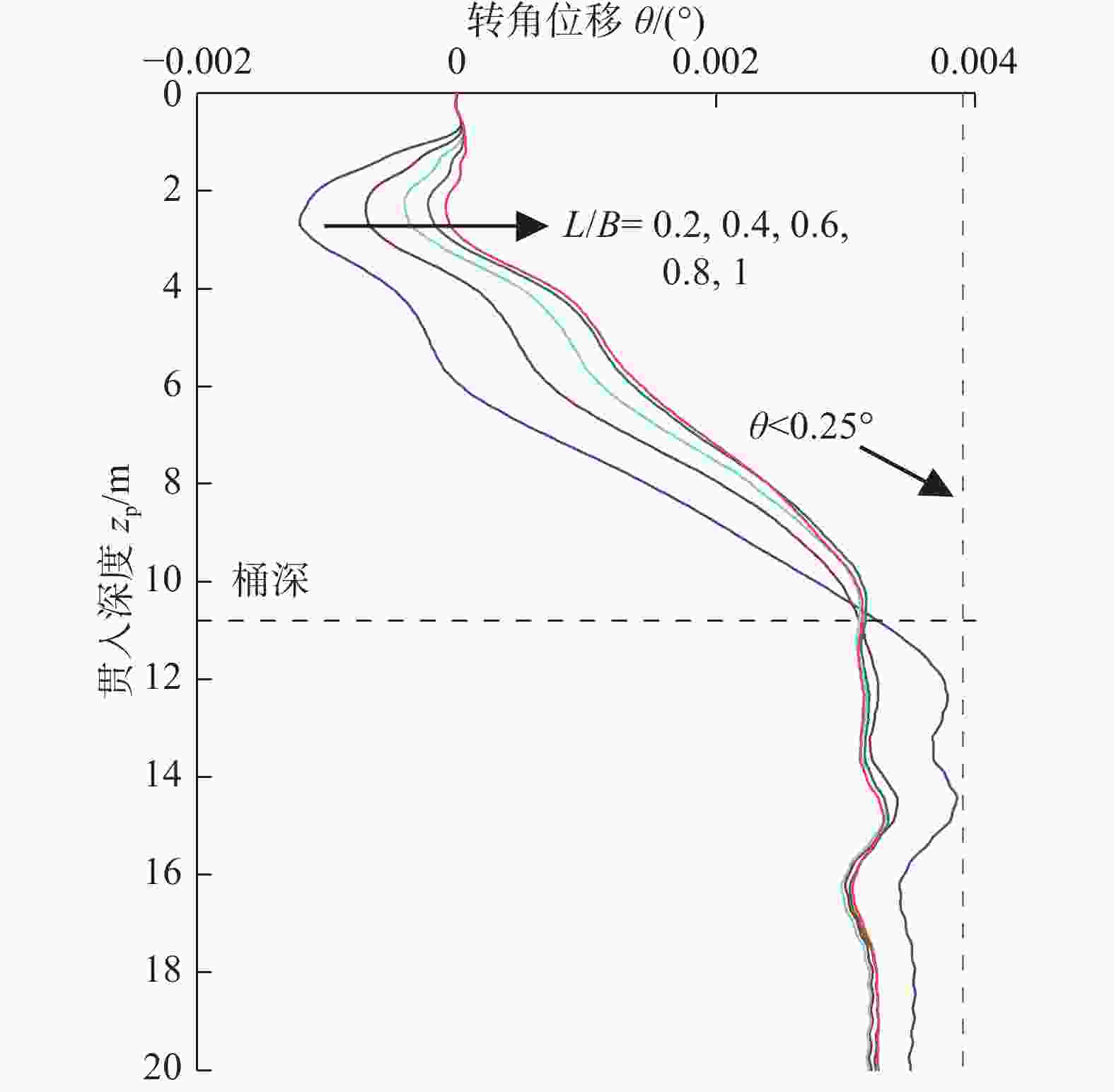
图 5 soil#1中转角位移随贯入深度演变规律
Figure 5. Evolution law of transition angle displacement with penetration depth in soil#1
同时,需要指出的是,转角位移最大值出现在L/B = 0.2工况12 m处,且在整个贯入过程中,最大值小于0.25°(~0.004 4 rad)。
-
图6展示了在soil#2(非均质黏土)中L/B = 0.2工况中的桩靴贯入过程周围土体速度矢量图。在本工况中,zp = 12 m为划分不同贯入阶段的深度。
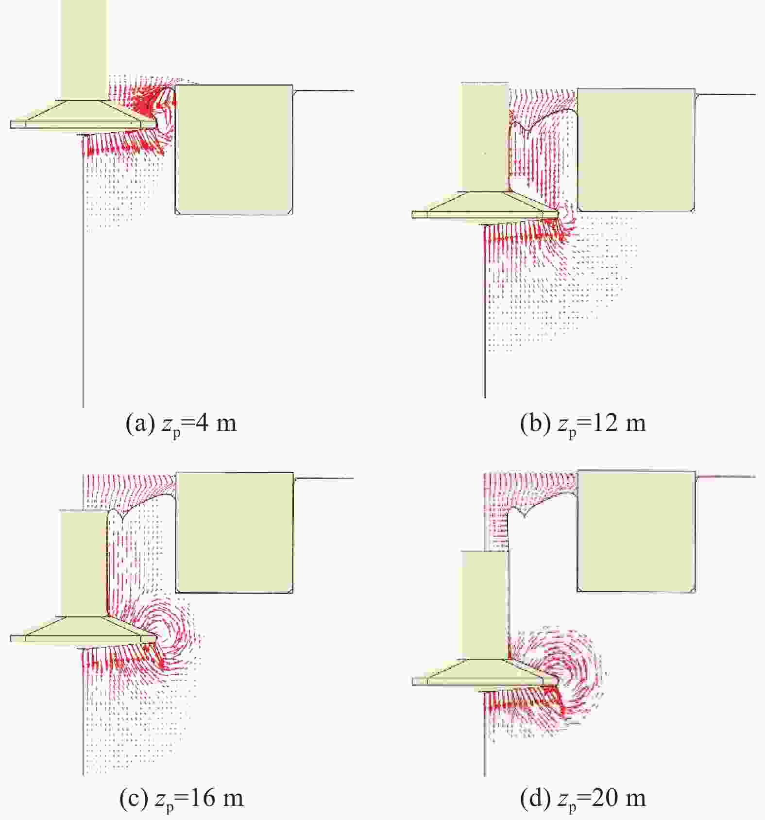
图 6 soil#2速度矢量图(非均质黏土、L/B = 0.2)
Figure 6. Velocity vector in soil#2 (non-homogeneous clay, L/B = 0.2)
在浅层贯入阶段中,图6(a)显示土体在重力的作用下,泥面的土体会迅速回流产生,并坍塌在桩靴上,桶壁附近的土体的流动方向以斜向下流动为主。之后,随着贯入深度的增加,土体局部脱离桶壁,桶壁附近的土体的流动方向以斜向上流动为主,如图6(b)所示。
在深层贯入阶段,桩靴的局部剪切破坏同样产生抬升力,如图6(c)所示。之后,不再对导管架基础产生影响。如图6(d)所示。
在soil#2工况中,转角位移同样会发生方向的改变,即逆时针到顺时针的改变。同样以L/B = 0.2工况为例,说明非均质黏土中基础转角位移。在土体流动影响下,0 – 4 m段,导管架仅发生极小幅度逆时针位移;在4 – 12 m段和12 – 16 m段,逆时针转动转为顺时针,且大幅度增加;当贯入深度增加到16 m时,转动位移不再发生改变。同样的,图7中显示,在不同L/B工况下,随着L/B逐渐减小,转角位移逐渐减小。与均质黏土不同的是,在贯入深度超过桶底深度段,不同L/B工况中的转角位移仍存在明显差异,且并不会收敛于同一位移,这是因为在soil#2中,由于土体较软,会产生明显的坍塌现象,且随着净间距的增加,土体的坍塌范围有所增加,进而影响三桶导管架基础的倾覆位移量。
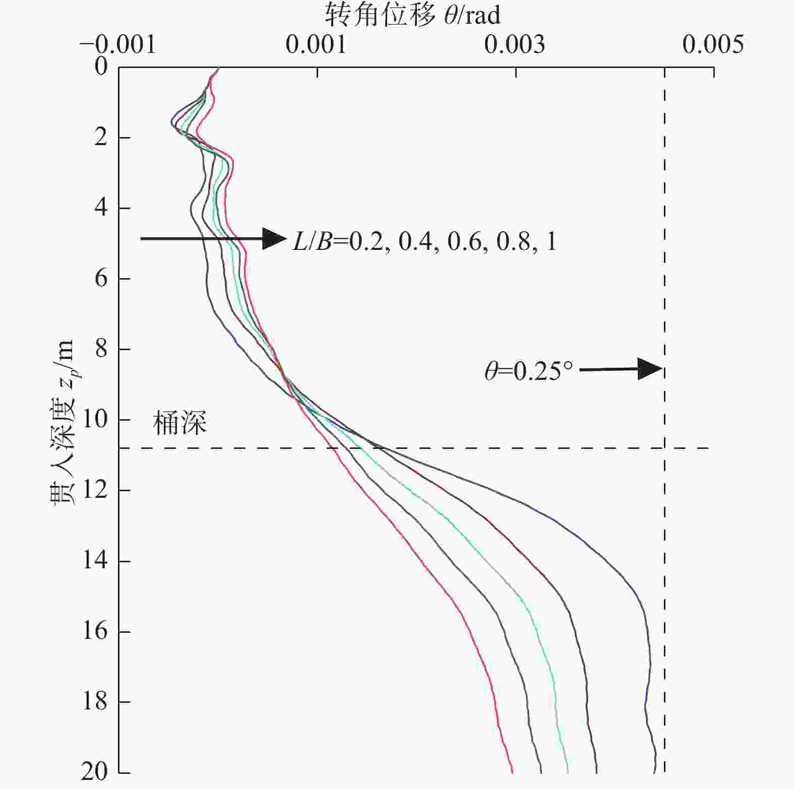
图 7 soil#2中转角位移随贯入深度演变规律
Figure 7. Evolution law of transition angle displacement with penetration depth in soil#2
与均质黏土一致的是,在整个贯入过程中,转角位移最大值同样出现于L/B = 0.2工况中,16 m处,且小于0.25°(~0.004 4 rad)。
-
土体的软化效应是指土体在外部荷载下,土体中产生累积塑性应变,其抗剪强度发生降低的现象。针对完全软化区域,强度衰减系数取灵敏度的倒数,即β = 0.25;针对部分软化区域,强度衰减系数β表达式如式(3)[25]所示。
$$ \beta ={s}_{{\mathrm{u}}}/{s}_{\text{u}\text{0}}={\delta }_{{\mathrm{rem}}}+\left(1-{\delta }_{{\mathrm{rem}}}\right){e}^{\tfrac{-3\xi }{{\xi }_{95}}} $$ (3) 式中:
β ——强度衰减系数(无量纲);
su ——土体强度(kPa);
δrem ——灵敏度St的倒数(无量纲);
ξ ——土体累积塑性应变(无量纲);
ξ95 ——土体延展性系数,一般介于10 – 50[26]之间(无量纲)。
为获得较大的塑性应变,本文$ {\xi }_{95} $取10,从而产生显著的软化效应,以确保安装过程的安全性。
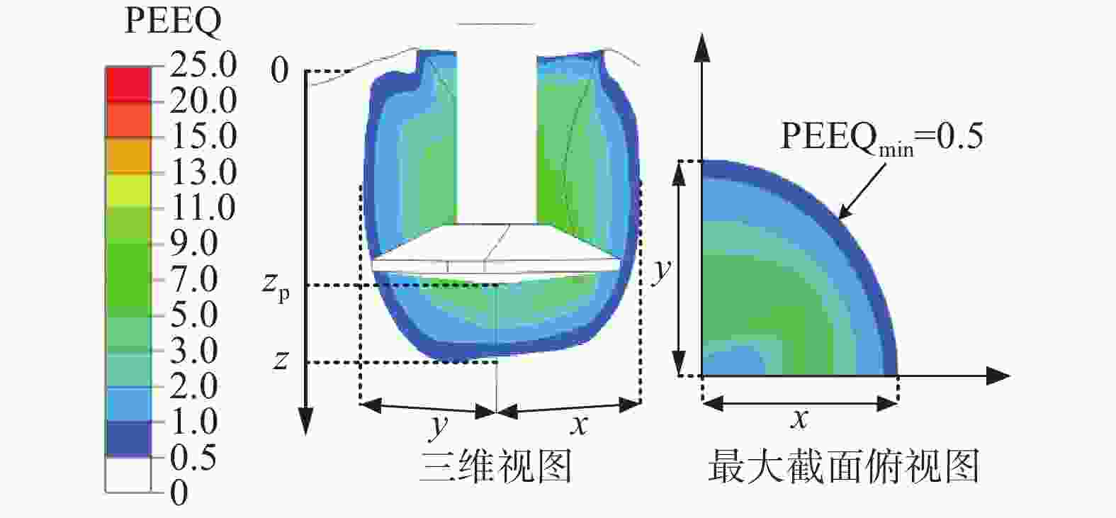
在部分软化区域范围内,可通过土体平均累积塑性应变值PEEQav来获得土体的强度衰减系数。土体的平均累积塑性应变值PEEQav由土体单位的体积分数EVF和PEEQ共同决定,即将各单元的EVF乘以相应PEEQ,然后加总求和得到总体值,再除以总的EVF。需要指出的是,当PEEQ = 0.5确定,此时对应的β = 90%,可忽略不计。
土体的软化范围测定如图8所示,通过该方法可以获得各方向的土体软化范围。
考虑到土体软化将影响桩靴拔出后的吸力桶服役性能,在本节中,选取桩靴完全拔出的深度确定相应的土体软化区域和程度,如表3所示。
表 3 土体部分软化区域和软化程度
Table 3. Softening zone and degree of soil
土体 软化程度 软化区域 备注 PEEQav βav x/B y/B (z−zp)/B soil#1 5.75 0.38 1.3 1.2 0.6 zp = 20 m Soil#2 7.75 0.32 1.5 1.5 0.3 -
为分析桩靴拔出后土体软化对吸力桶各向单轴承载力的影响,本文选取L/B = 0.2和1两种边界工况,采用位移加载法研究了邻近桶的水平向极限承载力Hult、弯矩极限承载力Mult和竖向极限承载力Vult;并提出了各向承载力折减系数α,其可被量化为考虑土体软化与未考虑土体软化的两个承载力比值,介于0~1。
表4详细展示了不考虑土体软化及考虑土体软化(L/B = 0.2 与L/B = 1)3个工况下的极限承载力,包括水平向极限承载力Hult,弯矩极限承载力Mult和竖向极限承载力Vult。L/B = 0.2与L/B = 1两个工况下的各向承载力折减系数α可被评估并展示在表中,以L/B = 0.2的水平向极限承载力Hult为例,承载力折减系数 α,α = 4.2/5.1 = 0.82。以soil#1为例,L/B = 1时各向承载力折减系数均大于94%,被认为当桩靴与桶间距满足L/B ≥ 1时,插拔桩对邻近桶的影响可被忽略。L/B = 0.2时,插拔桩后的邻近桶基水平、弯矩和竖向承载力分别衰减了18%,22%以及27%。各向承载力折减机理可通过对比考虑土体软化与否承载力破坏机理的差异性进行解释。
表 4 邻近桶各向单轴极限承载力及折减系数
Table 4. Uniaxial ultimate bearing capacity and reduction factor near each cylinder
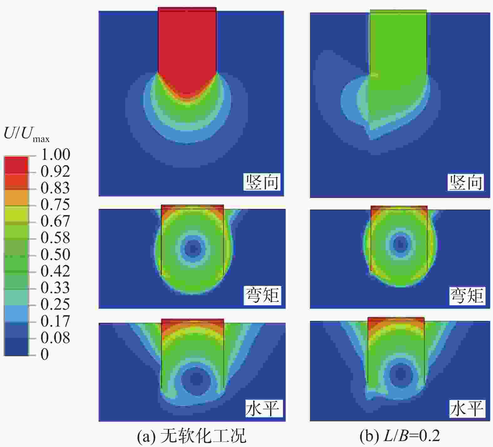
土体 工况 极限承载力 Hult/(MN) Mult/(MNm) Vult/(MN) soil#1 无软化 5.1 37.9 10.4 L/B = 0.2 4.2 29.7 8.2 L/B = 1 4.8 36.4 9.8 承载力折减系数α (0.82;0.96) (0.78;0.96) (0.73;0.94) soil#2 无软化 1.9 15.3 7.6 L/B = 0.2 1.5 11.5 5.5 L/B = 1 1.7 14.5 7.1 承载力折减系数α (0.79;0.89) (0.75;0.95) (0.72;0.93) 注:表中强度折减系数α=(a;b)分别对应工况(L/B = 0.2;L/B = 1) 图9展示了未考虑与考虑插拔桩后土体软化的邻近桶基各向承载力破坏模式的对比。为方便对比,将达到无软化下极限承载力时的土体最大位移定义为Umax,无量纲化后的土体位移为U/Umax = 0~1。从图中可以看出,L/B = 0.2工况下,相对于无软化情况,考虑土体软化后的桶基弯矩和水平向极限承载力土体破坏区域与无软化工况相类似,20%的承载力衰减反应了土体强度的衰减程度。而在竖向荷载作用下,桶周围竖向最大位移仅达到0.67Umax即到达极限承载力(破坏区域较无软化区域发生缩减),这导致了考虑土体软化后的竖向极限承载力更为明显的衰减(27%的衰减)。
-
本文利用CEL大变形技术研究了在均质和非均质黏土中桩靴贯入过程对邻近导管架基础的附加倾覆量的影响机制,并在考虑了土体软化效应后,分析了邻近桶基的承载力折减机理。结论如下:
1)临近三桶导管架基础的桩靴贯入过程基本可分为浅层整体剪切破坏和深层局部剪切破坏两个典型阶段,在强度非均质程度较大的黏土中,桩靴贯入产生的空穴更易从很浅的贯入深度开始发生回填,主要来自于桶侧壁周围的上层软土坍塌。
2)三桶导管架基础随桩靴贯入过程均发生先逆后顺的转动;且转角位移均随着L/B的增加而逐渐减小。在均质和非均质黏土中,最大倾覆角度位移均出现在L/B = 0.2工况,但强度非均质程度较大的黏土中,最大倾覆角所对应的贯入深度更大,但均小于安全阈值,即0.25°。
3)针对于完全拔出深度,在强度均质程度较大的黏土中,软化区域影响范围水平方向(x; y)较大(本文中均质土为1.5B;1.5B,非均质土为1.3B;1.2B),而在深度方向(z−zp)较小(本文中均质土为0.3B,非均质土为0.6B)。强度均质程度较大的黏土中,强度损失较小(本文中均质土折减系数0.38,非均质土为0.32)。在强度均质程度较大的黏土中,临近桶的水平向、转角向的最大承载力损失较少,而竖向承载力损失程度与非均质程度较大的黏土相当(本文中,均质土中水平向、转角向和竖向最大承载力折减系数为0.82;0.78和0.73;非均质土中为0.79;0.75和0.73)。
由于海床原状土性质复杂,其分层性会对桩靴插拔以及其邻近基础的承载力产生重要影响。本文只分析了均质和非均质黏土这种工况,在以后的研究中可对砂土及更为复杂的分层土体(黏砂互层)进行进一步研究。
Research on the Influence of Pile Shoe Insertion and Removal on the Neighboring Three-Cylinder Jacket Foundation in Clay
-
摘要:
目的 移动式平台进场安装海上风机的插拔桩施工过程风险大,易影响邻近基础结构的工作性能,甚至导致其失稳破坏。 方法 为厘清桩靴插拔过程对临近基础的影响机理,文章针对类矩形桩靴,采用CEL大变形方法,开展了其在均质和非均质黏土中插拔过程模拟,重点分析了插桩过程对邻近导管架基础产生的附加倾覆角演变机理;并基于大变形模拟结果,利用小变形进一步研究了桩靴拔出后土体软化效应对邻近桶各向极限承载力的影响。 结果 研究结果表明,在桩靴挤土作用下,三桶导管架基础均会发生先顺后逆的转动位移,且随着净间距的增加而逐渐减小。同时,挤土导致的土体软化会使邻近桶各向承载力降低。 结论 受插拔桩靴的影响,非均质土中的三桶导管架的倾覆角度更大,所对应的贯入深度更深。插拔桩靴所造成的软化区域影响范围在均质黏土中水平方向延伸较大,深度方向较小。在均质黏土中,平均强度损失较小,三桶导管架的水平向、转角向的承载力损失较少。在均质和非均质黏土中,竖向承载力折减明显,最大折减系数可达0.72。 Abstract:Introduction The construction process of pile insertion and removal for installing offshore wind turbines on mobile platforms is risky, which can easily affect the working performance of adjacent infrastructure, and even lead to its instability and failure. Method In order to clarify the mechanism of the influence of pile shoe insertion and removal on adjacent foundation, this paper used CEL large deformation method to simulate the insertion and removal process of similar rectangular pile shoe in homogeneous and heterogeneous clay, and focused on the analysis of the evolution mechanism of additional overturning angle caused by pile insertion process on adjacent jacket foundation; based on the simulation results of large deformation, the influence of soil softening effect on the ultimate bearing capacity of adjacent buckets after pile shoe removal was further studied by using small deformation. Result The results show that under the action of pile shoe compaction, the rotational displacement of the three-cylinder jacket foundation will take place, and it will decrease gradually with the increase of net spacing. At the same time, the soil softening caused by compaction will reduce the bearing capacity of adjacent cylinder. Conclusion The overturning angle of three-cylinder jacket in heterogeneous soil is larger and the corresponding penetration depth is deeper due to the influence of pile shoe insertion and removal. The affected area of softening area caused by pile shoe insertion and removal is larger in horizontal direction and smaller in depth direction in homogeneous clay. In homogeneous clay, the average strength loss is small, and the horizontal and angular bearing capacity loss of the three-cylinder jacket is small. In homogeneous and heterogeneous clays, the vertical bearing capacity is reduced obviously, and the maximum reduction factor can reach 0.72. -
Key words:
- pile shoe /
- large deformation /
- small deformation /
- softening effect /
- overturning /
- bearing capacity
-
表 1 土层材料特性
Tab. 1. Soil properties
土体 性质 su0/kPa γ/(kN·m−3) Soil#1 均质黏土 20 6 Soil#2 非均质黏土 1+z 6 表 2 小变形验证结果
Tab. 2. Validation results of small deformation
文献 承载力系数 水平向/NcH 弯矩向/NcM 竖向/NcV Liu等[23] 4.50 1.63 10.75 本模型 4.37 1.51 10.55 误差/% 2.90 7.85 1.90 表 3 土体部分软化区域和软化程度
Tab. 3. Softening zone and degree of soil
土体 软化程度 软化区域 备注 PEEQav βav x/B y/B (z−zp)/B soil#1 5.75 0.38 1.3 1.2 0.6 zp = 20 m Soil#2 7.75 0.32 1.5 1.5 0.3 表 4 邻近桶各向单轴极限承载力及折减系数
Tab. 4. Uniaxial ultimate bearing capacity and reduction factor near each cylinder
土体 工况 极限承载力 Hult/(MN) Mult/(MNm) Vult/(MN) soil#1 无软化 5.1 37.9 10.4 L/B = 0.2 4.2 29.7 8.2 L/B = 1 4.8 36.4 9.8 承载力折减系数α (0.82;0.96) (0.78;0.96) (0.73;0.94) soil#2 无软化 1.9 15.3 7.6 L/B = 0.2 1.5 11.5 5.5 L/B = 1 1.7 14.5 7.1 承载力折减系数α (0.79;0.89) (0.75;0.95) (0.72;0.93) 注:表中强度折减系数α=(a;b)分别对应工况(L/B = 0.2;L/B = 1) -
[1] 宋础, 刘汉中. 海上风力发电场开发现状及趋势 [J]. 电力勘测设计, 2006(2): 55-58. DOI: 10.3969/j.issn.1671-9913.2006.02.014. SONG C, LIU H Z. The development and trend of wind power plant at sea [J]. Electric power survey & design, 2006(2): 55-58. DOI: 10.3969/j.issn.1671-9913.2006.02.014. [2] HOSSAIN M S, HU Y, RANDOLPH M F, et al. Limiting cavity depth for spudcan foundations penetrating clay [J]. Géotechnique, 2005, 55(9): 679-690. DOI: 10.1680/geot.2005.55.9.679. [3] HOSSAIN M S, RANDOLPH M F. New mechanism-based design approach for spudcan foundations on single layer clay [J]. Journal of geotechnical and geoenvironmental engineering, 2009, 135(9): 1264-1274. DOI: 10.1061/(ASCE)GT.1943-5606.000 0054. [4] MARTIN C M, HOULSBY G T. Combined loading of spudcan foundations on clay: laboratory tests [J]. Géotechnique, 2000, 50(4): 325-338. DOI: 10.1680/geot.2000.50.4.325. [5] 潘泽华, 刘博, 刘东华. 可移动自升式平台的桩靴沉放安装研究 [J]. 南方能源建设, 2023, 10(1): 48-56. DOI: 10.16516/j.gedi.issn2095-8676.2023.01.006. PAN Z H, LIU B, LIU D H. Research on the penetration of spudcan foundation for mobile jack-up platform [J]. Southern energy construction, 2023, 10(1): 48-56. DOI: 10.16516/j.gedi.issn2095-8676.2023.01.006. [6] ZHANG Y H, WANG D, CASSIDY M J, et al. Effect of installation on the bearing capacity of a spudcan under combined loading in soft clay [J]. Journal of geotechnical and geoenvironmental engineering, 2014, 140(7): 459-477. DOI: 10.1061/(ASCE)GT.1943-5606.0001126. [7] 王凯, 武宗豪, 韩若朗, 等. 砂土中桩靴贯入深度对自升式风电安装船水平承载特性影响的试验研究 [J]. 南方能源建设, 2023, 10(4): 1-10. DOI: 10.16516/j.gedi.issn2095-8676.2023.04.001. WANG K, WU Z H, HAN R L, et al. Model test study on the influence of the spudcan penetration depth on the horizontal bearing characteristics of jack-up vessel for wind turbine installation in sandy soil [J]. Southern energy construction, 2023, 10(4): 1-10. DOI: 10.16516/j.gedi.issn2095-8676.2023.04.001. [8] YUN G, BRANSBY M F. The horizontal-moment capacity of embedded foundations in undrained soil [J]. Canadian geotechnical journal, 2007, 44(4): 409-424. DOI: 10.1139/t06-126. [9] 肖忠. 深埋式大圆筒防波堤稳定性分析的极限平衡法 [C]//中国力学大会-2017暨庆祝中国力学学会成立60周年大会论文集(A), 北京, 2017-08-13. 北京: 中国力学学会, 2017: 1220-1229. XIAO Z. Stability analysis of deeply embedded large cylindrical breakwater based on limit equilibrium method [C]//Chinese Congress of Mechanics-2017 Proceedings of the Conference Celebrating the 60th Anniversary of the Founding of the Chinese Society of Mechanics (A), Beijing, August 13, 2017. Beijing: The Chinese Society of Theoretical and Applied Mechanics, 2017: 1220-1229. [10] FU D F, GAUDIN C, TIAN Y H, et al. Uniaxial capacities of skirted circular foundations in clay [J]. Journal of geotechnical and geoenvironmental engineering, 2017, 143(7): 04017022. DOI: 10.1061/(ASCE)GT.1943-5606.0001685. [11] HUNG L C, KIM S R. Evaluation of undrained bearing capacities of bucket foundations under combined loads [J]. Marine georesources & geotechnology, 2014, 32(1): 76-92. DOI: 10.1080/1064119x.2012.735346. [12] MANA D S K, GOURVENEC S, RANDOLPH M F. Experimental investigation of reverse end bearing of offshore shallow foundations [J]. Canadian geotechnical journal, 2013, 50(10): 1022-1033. DOI: 10.1139/cgj-2012-0428. [13] XIE Y. Centrifuge model study on spudcan-pile interaction [D]. Singapore: National University of Singapore, 2009. [14] THO K K, CHAN N, PAISLEY J. Comparison of coupled and decoupled approaches to spudcan-pile interaction [C]//Frontiers in Offshore Geotechnics, London, 2015: 1317-1322. DOI: 10.1201/b18442-200. [15] ZHANG H Y, LIU R, YUAN Y. Influence of spudcan-pile interaction on laterally loaded piles [J]. Ocean engineering, 2019, 184: 32-39. DOI: 10.1016/j.oceaneng.2019.05.022. [16] FAN Y F, WANG J H, FENG S L. Effect of spudcan penetration on laterally loaded pile groups [J]. Ocean engineering, 2021, 221: 108505. DOI: 10.1016/j.oceaneng.2020.108505. [17] XIAO Z, LU Y M, WANG Y Z, et al. Investigation into the influence of caisson installation process on its capacities in clay [J]. Applied ocean research, 2020, 104: 102370. DOI: 10.1016/j.apor.2020.102370. [18] ZHANG Y H, BIENEN B, CASSIDY M J, et al. The undrained bearing capacity of a spudcan foundation under combined loading in soft clay [J]. Marine structures, 2011, 24(4): 459-477. DOI: 10.1016/j.marstruc.2011.06.002. [19] 戴笑如, 王建华, 范怡飞. 钻井船插桩CEL数值模拟中的若干问题分析 [J]. 岩土力学, 2018, 39(6): 2278-2286. DOI: 10.16285/j.rsm.2016.2142. DAI X R, WANG J H, FAN Y F. Issues of numerical simulation of the spudcan penetration based on CEL method [J]. Rock and soil mechanics, 2018, 39(6): 2278-2286. DOI: 10.16285/j.rsm.2016.2142. [20] THO K K, LEUNG C F, CHOW Y K, et al. Eulerian finite-element technique for analysis of jack-up spudcan penetration [J]. International journal of geomechanics, 2012, 12(1): 64-73. DOI: 10.1061/(asce)gm.1943-5622.0000111. [21] HOSSAIN M. New mechanism-based design approaches for spudcan foundations in clay [D]. Perth: The University of Western Australia, 2008. [22] 肖忠, 王琰, 王元战, 等. 桶间距对四桶吸力式基础各单向承载力的影响及最优间距的确定 [J]. 岩土力学, 2018, 39(10): 3603-3611. DOI: 10.16285/j.rsm.2017.2277. XIAO Z, WANG Y, WANG Y Z, et al. Effect of bucket separation distance on bearing capacity of tetrapod bucket foundations and determination of optimal separation distance [J]. Rock and soil mechanics, 2018, 39(10): 3603-3611. DOI: 10.16285/j.rsm.2017.2277. [23] LIU R, YUAN Y, FU D F, et al. Geotechnical capacities of large-diameter cylindric foundations in clay under general loadings [J]. Applied ocean research, 2021, 117: 102951. DOI: 10.1016/j.apor.2021.102951. [24] SNAME. Recommended practice for site specific assessment of mobile jack-up units [M]. New Jersey: Society of Naval Architects and Marine Engineers, Technical and Research Bulletin5-5A, 2008: 64-109. [25] EINAV I, RANDOLPH M F. Combining upper bound and strain path methods for evaluating penetration resistance [J]. International journal for numerical methods in engineering, 2005, 63(14): 1991-2016. DOI: 10.1002/nme.1350. [26] ZHOU H, RANDOLPH M F. Penetration of full-flow penetrometers in rate-dependent and strain-softening clay [J]. Géotechnique, 2009, 59(2): 79-86. DOI: 10.1680/geot.2007.00164. -


 下载:
下载:
