• Peer Review
  • Non-profit
  • Global Open Access
  • Green Channel for Rising Stars
Volume 9 Issue S2
Jan.  2023
Turn off MathJax
Article Contents

XIE Nan, YANG Peihao, HE Ping, CHEN Yao. Research on VSG Control Strategy for Energy Storage Microgrid Based on Virtual Impedance[J]. SOUTHERN ENERGY CONSTRUCTION, 2022, 9(S2): 90-97. doi: 10.16516/j.gedi.issn2095-8676.2022.S2.015
Citation: XIE Nan, YANG Peihao, HE Ping, CHEN Yao. Research on VSG Control Strategy for Energy Storage Microgrid Based on Virtual Impedance[J]. SOUTHERN ENERGY CONSTRUCTION, 2022, 9(S2): 90-97. doi: 10.16516/j.gedi.issn2095-8676.2022.S2.015

Research on VSG Control Strategy for Energy Storage Microgrid Based on Virtual Impedance

doi: 10.16516/j.gedi.issn2095-8676.2022.S2.015
  • Received Date: 2022-02-25
  • Rev Recd Date: 2022-06-07
  • Available Online: 2023-01-04
  • Publish Date: 2023-01-04
  •   Introduction  In order to make the grid-connected power conversion system (PCS) for the energy storage microgrid has the same rotation and excitation characteristics as the synchronous generator, the virtual synchronous generation (VSG) control strategy is proposed in the grid-connected PCS control system for the energy storage microgrid.   Method  In this paper, in view of the fact that the traditional VSG did not have the low voltage ride through (LVRT) capability, the virtual impedance reactive power control link of VSG was constructed to modify the voltage control input signal in real time and improve the support ability of system transient voltage drop. In order to obtain the amplitude and resistance inductance ratio of virtual impedance, LVRT operating conditions were divided into symmetrical and asymmetrical short-circuit failures of the line, and the positive and negative sequence voltage and current were studied to obtain the virtual impedance parameters.   Result  In order to verify the performance of the proposed control strategy, simulation is performed using Matlab/Simulink, and the simulation conditions are set as follows: three-phase grounding and single-phase grounding faults occur in the external transmission line of the energy storage microgrid respectively.   Conclusion  The simulation results show that the introduction of virtual impedance into VSG control system can improve the output voltage of the grid-connected PCS for the energy storage microgrid in case of short circuit, play the role of voltage transient support during LVRT, make the energy storage microgrid has LVRT capability, and provide guidance for practical application.
  • [1] 孙钢虎, 王小辉, 陈远志, 等. 储能联合发电机组调频经济效益分析 [J]. 电源学报, 2020, 18(4): 151-156. DOI:  10.13234/j.issn.2095-2805.2020.4.151.

    SUN G H, WANG X H, CHEN Y Z, et al. Analysis of economic benefits of frequency modulation by energy storage combined generating units [J]. Journal of Power Supply, 2020, 18(4): 151-156. DOI:  10.13234/j.issn.2095-2805.2020.4.151.
    [2] 王鑫明, 寻志伟, 杨沛豪. 电转气技术的应用及与其它储能方式的比较 [J]. 上海电气技术, 2019, 12(1): 18-22. DOI:  10.3969/j.issn.1674-540X.2019.01.005.

    WANG X M, XUN Z W, YANG P H. Application of electric gas conversion technology and comparison with other energy storage schemes [J]. Journal of Shanghai Electric Technology, 2019, 12(1): 18-22. DOI:  10.3969/j.issn.1674-540X.2019.01.005.
    [3] 印佳敏, 郑赟, 杨劲. 储能火电联合调频的容量优化配置研究 [J]. 南方能源建设, 2020, 7(4): 11-17. DOI:  10.16516/j.gedi.issn2095-8676.2020.04.002.

    YIN J M, ZHENG Y, YANG J. Research on capacity optimization of generator-storage combined frequency regulation system [J]. Southern Energy Construction, 2020, 7(4): 11-17. DOI:  10.16516/j.gedi.issn2095-8676.2020.04.002.
    [4] 沈迎, 黄策, 胡锡东, 等. 锂离子电容器参与火电机组调频研究 [J]. 电气技术, 2021, 22(10): 98-103. DOI:  10.3969/j.issn.1673-3800.2021.10.018.

    SHEN Y, HUANG C, HU X D, et al. Research on frequency regulation of thermal power unit with lithium-ion capacitor [J]. Electrical Engineering, 2021, 22(10): 98-103. DOI:  10.3969/j.issn.1673-3800.2021.10.018.
    [5] 鲍建, 杨沛豪, 何昭辉, 等. 新能源混合储能提高高电压穿越能力研究 [J]. 热力发电, 2021, 50(8): 79-86. DOI:  10.19666/j.rlfd.202103044.

    BAO J, YANG P H, HE Z H, et al. Research on improving high voltage ride through capability of new energy hybrid energy storage system [J]. Thermal Power Generation, 2021, 50(8): 79-86. DOI:  10.19666/j.rlfd.202103044.
    [6] GAO F, WANG X H, YANG P H, et al. Research and simulation of hybrid AC/DC microgrid [C]//Proceedings of the 2020 4th International Conference on HVDC. Xi'an, China: IEEE, 2020: 1276-1280. DOI:  10.1109/HVDC50696.2020.9292793.
    [7] 高啸天, 匡俊, 楚攀, 等. 化学电源及其在储能领域的应用 [J]. 南方能源建设, 2020, 7(4): 1-10. DOI:  10.16516/j.gedi.issn2095-8676.2020.04.001.

    GAO X T, KUANG J, CHU P, et al. Chemical power sources and their applications in energy storage fields [J]. Southern Energy Construction, 2020, 7(4): 1-10. DOI:  10.16516/j.gedi.issn2095-8676.2020.04.001.
    [8] HUO J X, JI H J, YANG P H. Research on sensorless control system of permanent magnet synchronous motor for CNC machine tool [C]//Proceedings of the 2021 40th Chinese Control Conference. Shanghai, China: IEEE, 2021: 1592-1595. DOI:  10.23919/CCC52363.2021.9550563.
    [9] 耿昊翔, 王维俊, 唐帅, 等. 基于无锁相环的虚拟同步发电机离并网切换控制策略研究 [J]. 电机与控制应用, 2021, 48(9): 90-95. DOI:  10.12177/emca.2021.072.

    GENG H X, WANG W J, TANG S, et al. Research on off-grid/on-grid switching control strategy of virtual synchronous generator without PLL [J]. Electric Machines & Control Application, 2021, 48(9): 90-95. DOI:  10.12177/emca.2021.072.
    [10] 黄子远. 基于双自适应参数混合微网虚拟同步机控制策略研究 [D]. 南宁: 广西大学, 2021. DOI: 10.27034/d.cnki.ggxiu.2021.000607.

    HUANG Z Y. Control strategy of hybrid microgrid virtual synchronous machine based on dual adaptive parameters [D]. Nanning: Guangxi University, 2021. DOI: 10.27034/d.cnki.ggxiu.2021.000607.
    [11] 劳永钊, 吴任博, 肖健, 等. 基于同步相量测量的配电网电压暂降溯源系统设计研究 [J]. 南方能源建设, 2022, 9(1): 115-121. DOI:  10.16516/j.gedi.issn2095-8676.2022.01.017.

    LAO Y Z, WU R B, XIAO J, et al. Research on voltage sag source-locating system design of distribution network based on synchronous phasor measurement [J]. Southern Energy Construction, 2022, 9(1): 115-121. DOI:  10.16516/j.gedi.issn2095-8676.2022.01.017.
    [12] 季宇, 苏剑, 丁保迪, 等. 直流微电网储能系统的无源-滑模复合控制方法研究 [J]. 电测与仪表, 2021, 58(9): 63-70. DOI:  10.19753/j.issn1001-1390.2021.09.010.

    JI Y, SU J, DING B D, et al. Research on passive based control combined SMC control of DC micro-grid energy storage system [J]. Electrical Measurement & Instrumentation, 2021, 58(9): 63-70. DOI:  10.19753/j.issn1001-1390.2021.09.010.
    [13] 王小辉, 刘向辰, 寇水潮, 等. 基于两步模型预测控制的ACIM电流控制方法 [J]. 电力电子技术, 2019, 53(8): 52-55.

    WANG X H, LIU X C, KOU S C, et al. Current control method for ACIM based on two-step model predictive control [J]. Power Electronics, 2019, 53(8): 52-55.
    [14] 秦晓辉, 苏丽宁, 迟永宁, 等. 大电网中虚拟同步发电机惯量支撑与一次调频功能定位辨析 [J]. 电力系统自动化, 2018, 42(9): 36-43. DOI:  10.7500/AEPS20171122007.

    QIN X H, SU L N, CHI Y N, et al. Functional orientation discrimination of inertia support and primary frequency regulation of virtual synchronous generator in large power grid [J]. Automation of Electric Power Systems, 2018, 42(9): 36-43. DOI:  10.7500/AEPS20171122007.
    [15] 涂娟, 赵翔. 电网故障下风力发电系统网侧电压同步信号检测 [J]. 电机与控制应用, 2020, 47(3): 81-86. DOI:  10.12177/emca.2019.173.

    TU J, ZHAO X. Synchronizing signal detection of grid voltage in wind power generation systems under grid faults [J]. Electric Machines & Control Application, 2020, 47(3): 81-86. DOI:  10.12177/emca.2019.173.
  • 通讯作者: 陈斌, bchen63@163.com
    • 1. 

      沈阳化工大学材料科学与工程学院 沈阳 110142

    1. 本站搜索
    2. 百度学术搜索
    3. 万方数据库搜索
    4. CNKI搜索

Figures(10)  / Tables(5)

Article Metrics

Article views(170) PDF downloads(51) Cited by()

Related

Research on VSG Control Strategy for Energy Storage Microgrid Based on Virtual Impedance

doi: 10.16516/j.gedi.issn2095-8676.2022.S2.015

Abstract:   Introduction  In order to make the grid-connected power conversion system (PCS) for the energy storage microgrid has the same rotation and excitation characteristics as the synchronous generator, the virtual synchronous generation (VSG) control strategy is proposed in the grid-connected PCS control system for the energy storage microgrid.   Method  In this paper, in view of the fact that the traditional VSG did not have the low voltage ride through (LVRT) capability, the virtual impedance reactive power control link of VSG was constructed to modify the voltage control input signal in real time and improve the support ability of system transient voltage drop. In order to obtain the amplitude and resistance inductance ratio of virtual impedance, LVRT operating conditions were divided into symmetrical and asymmetrical short-circuit failures of the line, and the positive and negative sequence voltage and current were studied to obtain the virtual impedance parameters.   Result  In order to verify the performance of the proposed control strategy, simulation is performed using Matlab/Simulink, and the simulation conditions are set as follows: three-phase grounding and single-phase grounding faults occur in the external transmission line of the energy storage microgrid respectively.   Conclusion  The simulation results show that the introduction of virtual impedance into VSG control system can improve the output voltage of the grid-connected PCS for the energy storage microgrid in case of short circuit, play the role of voltage transient support during LVRT, make the energy storage microgrid has LVRT capability, and provide guidance for practical application.

XIE Nan, YANG Peihao, HE Ping, CHEN Yao. Research on VSG Control Strategy for Energy Storage Microgrid Based on Virtual Impedance[J]. SOUTHERN ENERGY CONSTRUCTION, 2022, 9(S2): 90-97. doi: 10.16516/j.gedi.issn2095-8676.2022.S2.015
Citation: XIE Nan, YANG Peihao, HE Ping, CHEN Yao. Research on VSG Control Strategy for Energy Storage Microgrid Based on Virtual Impedance[J]. SOUTHERN ENERGY CONSTRUCTION, 2022, 9(S2): 90-97. doi: 10.16516/j.gedi.issn2095-8676.2022.S2.015
    • 随着新能源装机容量的不断提升,区域电网结构越发复杂,传统微电网由光伏、风电等高渗透率分布式电源点组成,具有低惯性、低阻尼的特性[1-2]。储能单元作为可以灵活充放电的电源,配置在微电网并网PCS直流侧,可以实现能量动态吸收、释放[3-4]。为了使储能微网具备同步发电机特性,为电网提供惯性和阻尼支撑,目前广泛采用VSG控制方法[5-7]

      传统VSG无法对系统提供暂态电压支撑,所以不具备LVRT能力。当网侧发生接地故障,造成系统电压对称或者不对称跌落事故时,储能微网设备极易脱网[8-10]。劳永钊[11]以网侧三相电压不平衡为研究对象,将新能源微网输出正序、负序电流进行解耦,分别提出相应并网冲击电流抑制方法。为了提高对LVRT期间的电流跟踪能力,季宇[12]将滑模观测器应用于储能PCS矢量电流环中,实现电流无差调节。王小辉[13]采用模型预测有限控制方法,根据光伏并网逆变器开关离散特性,不断优化增益开环特性,实现并网点电压支撑。秦晓辉[14]对阻尼系数进行改进,应用自适应阻尼在风机转子励磁控制系统中,可以有效抑制网侧电压骤升带来的转子电流震荡。涂娟[15]将VSG控制参数即虚拟惯量、阻尼系数与电压、电流闭环建立关系,选择合适的参数来抑制电压突降时候参数偏差。

      本文针对储能微网LVRT电压暂态特性差问题,提出一种基于虚拟阻抗的储能微网VSG控制策略。首先建立储能微网PCS的VSG控制模型;然后引入虚拟阻抗到VSG无功-电压控制中,起到故障期间电压支撑作用;接着将LVRT工况分为储能外接输电线路对称和不对称接地故障,分析对应正序电压、电流,负序电压、电流,进而得到虚拟阻抗幅值及阻感比参数;最后通过仿真验证本文所提方案的有效性和可行性。

    • 图1为含有分布式电源点及储能单元的微网拓扑图。光伏发电系统和风力发电系统构成分布式电源点,光伏阵列通过DC/DC换流器并入直流汇流母线,风电机组通过AC/DC换流器并入直流汇流母线。储能单元通过DC/DC换流器并入直流汇流母线,储能单元作为能量储存装置可以实现整个微网电能稳定外送/吸收。微网直流汇流母线通过DC/AC并网换流器及升压变与大电网相连。在DC/AC并网换流器中采用VSG控制策略,可以使储能微网具备旋转电动机惯性特性,为电网提供惯性和阻尼支撑。

      Figure 1.  Topology of microgrid with distributed power points and energy storage units

      建立储能微网PCS的LCL电路拓扑模型如图2。其中:Cdc为直流侧滤波电筒;RfLfCf构成滤波电路;uabciabc为PCS交流三相桥臂电压、电流;eabc为PCS并网点三相电压;LgRg构成线路阻抗。

      Figure 2.  LCL circuit topology of PCS for energy storage microgrid

      以储能微网向交流主网功率传输方向为正,储能微网PCS输出有功、无功功率为:

      $$ \left\{ \begin{gathered} P = \dfrac{E}{{R_{\text{g}}^2 + X_{\text{g}}^2}}\left( {{R_{\text{g}}}U\cos \delta + {X_{\text{g}}}U\sin \delta - {R_{\text{g}}}E} \right) \\ Q = \dfrac{E}{{R_{\text{f}}^2 + X_{\text{g}}^2}}\left( { - {R_{\text{g}}}U\sin \delta + {X_{\text{g}}}U\cos \delta - {X_{\text{g}}}E} \right) \\ \end{gathered} \right. $$ (1)

      式中:

      Xg ——线路电感Lg对应的感抗(mH);

      U ——PCS交流三相桥臂电压幅值(V);

      E ——PCS并网点三相电压幅值(V);

      δ ——功角(°)。

      输电线路成主感性,即感抗远大于阻抗(Xg>Rg)。储能微网并网情况下,PCS输出电压与网侧电压无相角差(δ≈0°),则有:sinδδ,cosδ≈0。

      储能微网PCS输出有功、无功功率简化为:

      $$ \left\{ \begin{gathered} P = \dfrac{{EU}}{{{X_{\text{g}}}}}\delta \\ Q = - \dfrac{{{E^2}}}{{{X_{\text{g}}}}} \\ \end{gathered} \right. $$ (2)

      根据式(2)可知:储能微网PCS输出有功功率与功角存在线性关系,无功功率与储能微网PCS并网点电压幅值呈线性关系,基于此,可以实现功率解耦控制。

    • 本文在储能微网PCS控制系统中,采用VSG控制策略,图3为储能微网PCS的VSG控制框图。

      Figure 3.  VSG control block diagram of PCS for energy storage microgrid

      图3中:PeQe分别为储能微网PCS有功、无功功率实际输出值;PrefQref分别为有功、无功功率目标值;θω分别为VSG虚拟电角度、虚拟电角速度,存在${\rm{d}}\theta /{\rm{d}}t = \omega $uV为VSG虚拟内电势。

      储能PCS的VSG转子机械方程为:

      $$ J\dfrac{{{\rm{d}}\omega }}{{{\rm{d}}t}} = {T_{\text{m}}} - {T_{\text{e}}} - {T_{\text{d}}} = \frac{1}{\omega }\left( {{P_{{\text{ref}}}} - {P_{\text{e}}}} \right) - D\left( {\omega - {\omega _0}} \right) $$ (3)

      式中:

      JD ——VSG虚拟转动惯量、阻尼系数;

      TmTeTd ——机械转矩、电磁转矩及阻尼转矩(N·m);

      ω0 ——额定虚拟角速度(rad/s)。

      VSG有功功率本质是在有功-频率下垂控制基础上引入虚拟转动惯量J具备同步发电机的旋转惯性。同时引入阻尼系数D来抑制电网功率调节过程中的振荡现象。

      VSG同样可以模拟同步发电机励磁电流控制方式实现电压幅值调节,具备励磁调节惯性。类比于储能PCS的VSG转子机械方程,可以得到无功-电压调节方程为:

      $$ {K_{\rm{u}}}\frac{{{\rm{d}}\Delta U}}{{{\rm{d}}t}} = \left( {{Q_{{\text{ref}}}} - {Q_{\text{e}}}} \right){\text{ + }}{K_Q}\left( {{u_{\rm{d}}} - {u_{{\text{V}}{\rm{d}}}}} \right) $$ (4)

      式中:

      Ku ——无功等效惯性系数;

      ΔU ——电无功-电压调节量(V);

      KQ ——无功-电压调节系数;

      ud ——dq坐标系下d轴PCS桥臂电压有效值(V);

      uVd ——dq坐标系下d轴VSG虚拟内电势(V)。

    • 根据图2储能微网PCS的LCL电路拓扑图,基于基尔霍夫电压定律可得:

      $$ L\frac{{{\rm{d}}{i_{{\text{abc}}}}}}{{{\rm{d}}t}} = {u_{{\text{abc}}}} - {i_{{\text{abc}}}}R - {e_{{\text{abc}}}} $$ (5)

      式中:

      L ——等效电感(mH),L=Lf+Lg

      R ——等效电阻(Ω),R=Rf+Rg

      定义Tabc→dq0为Park变换矩阵,则储能微网PCS交流三相桥臂电压、电流并网点三相电压可转换为:

      $$ \left\{ \begin{gathered} {\left[ {{u_{\rm{d}}}\;{u_{\rm{q}}}} \right]^{\text{T}}} = {T_{{\text{abc}} \to {\rm{dq}}{\text{0}}}}{\left[ {{u_{\text{a}}}\;{u_{\text{b}}}\;{u_{\text{c}}}} \right]^{\text{T}}} \\ {\left[ {{i_{\rm{d}}}\;{i_{\rm{q}}}} \right]^{\text{T}}} = {T_{{\text{abc}} \to {\rm{dq}}{\text{0}}}}{\left[ {{i_{\text{a}}}\;{i_{\text{b}}}\;{i_{\text{c}}}} \right]^{\text{T}}} \\ {\left[ {{e_{\rm{d}}}\;{e_{\rm{q}}}} \right]^{\text{T}}} = {T_{{\text{abc}} \to {\rm{dq}}{\text{0}}}}{\left[ {{e_{\text{a}}}\;{e_{\text{b}}}\;{e_{\text{c}}}} \right]^{\text{T}}} \\ \end{gathered} \right. $$ (6)

      将式(6)带入式(5),可以得到储能微网PCS在dq两相坐标系下的数学模型为:

      $$ \left\{ \begin{gathered} {u_{\rm{d}}} = {e_{\rm{d}}} + L\dfrac{{{\rm{d}}{i_{\rm{d}}}}}{{{\rm{d}}t}} + {i_{\rm{d}}}R - \omega L{i_{\rm{q}}} \\ {u_{\rm{q}}} = {e_{\rm{q}}} + L\dfrac{{{\rm{d}}{i_{\rm{q}}}}}{{{\rm{d}}t}} + {i_{\rm{q}}}R + \omega L{i_{\rm{d}}} \\ \end{gathered} \right. $$ (7)

      电流闭环调节采用PI控制方式,传递函数为:

      $$ \left\{ \begin{gathered} {u_{\rm{d}}} = \left( {{K_{\text{P}}} + \dfrac{{{K_{\text{I}}}}}{s}} \right)\left( {i_{\rm{d}}^* - {i_{\rm{d}}}} \right) - \omega L{i_{\rm{q}}} + {e_{\rm{d}}} \\ {u_{\rm{q}}} = \left( {{K_{\text{P}}} + \dfrac{{{K_{\text{I}}}}}{s}} \right)\left( {i_{\rm{q}}^ * - {i_{\rm{q}}}} \right) - \omega L{i_{\rm{d}}} + {e_{\rm{q}}} \\ \end{gathered} \right. $$ (8)

      式中:

      KpKI ——电流闭环PI调节控制中比例调节系数、积分调节系数;

      id*iq* ——对应电流参考值(A)。

    • 储能微网PCS的VSG控制系统正常工作时,PCS输出电压实时跟踪网侧电压。当网侧发生对侧短路或者不对称短路时,即单相、两相或三相短路接地故障,外接线路阻抗降低,电压大幅下跌,储能微网PCS并网点电压变化量为:

      $$ \left\{ \begin{gathered} \Delta {u_{\rm{d}}} = {u_{\rm{d}}} - u_{\rm{d}}^ * \\ \Delta {u_{\rm{q}}} = {u_{\rm{q}}} - u_{\rm{q}}^ * \\ \end{gathered} \right. $$ (9)

      式中:

      ud*uq*——发生短路时,uduq电压目标值(V)。

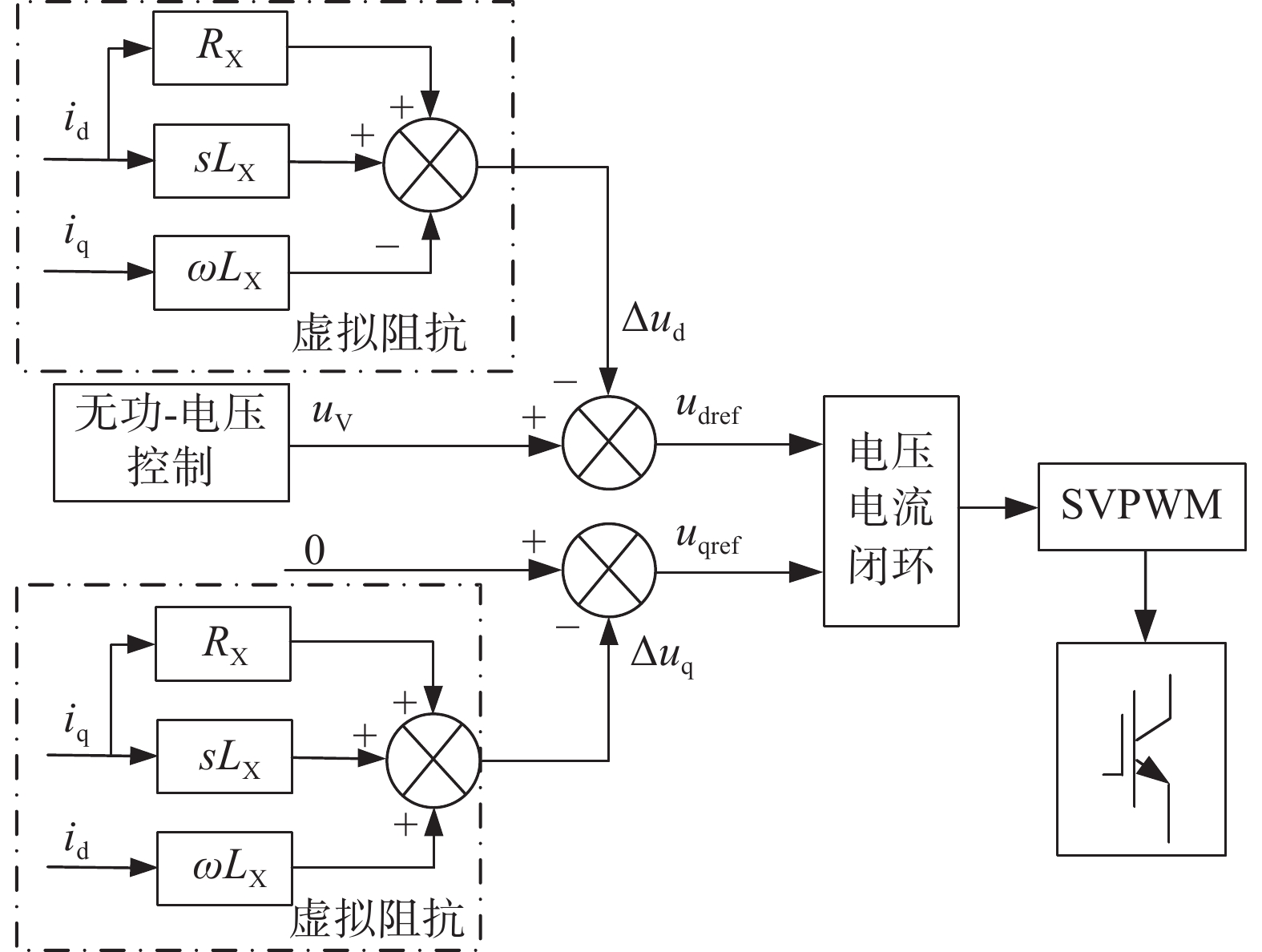
      本文采用虚拟阻抗来补偿Δud、Δuq,增加储能PCS的VSG控制系统LVRT能力,虚拟阻抗构造为:

      $$ {Z_{{\rm{X}}}}\left( s \right) = - {R_{{\rm{X}}}} + s{L_{{\rm{X}}}} $$ (10)

      式中:

      RX ——虚拟电阻(Ω);

      LX ——虚拟电感(mH)。

      dq坐标系下,ZX补偿压降为:

      $$ \left\{ \begin{gathered} \Delta {u_{\rm{d}}} = {L_{{\rm{X}}}}\frac{{{{\rm{d}}}{i_{\rm{d}}}}}{{{\rm{d}}t}} + {R_{{\rm{X}}}}{i_{\rm{d}}} - \omega {L_{{\rm{X}}}}{i_{\rm{q}}} \\ \Delta {u_{\rm{q}}} = {L_{{\rm{X}}}}\frac{{{{\rm{d}}}{i_{\rm{q}}}}}{{{\rm{d}}t}} + {R_{{\rm{X}}}}{i_{\rm{q}}} + \omega {L_{{\rm{X}}}}{i_{\rm{d}}} \\ \end{gathered} \right. $$ (11)

      将虚拟阻抗ZX补偿压降带入储能微网PCS的VSG无功-电压调节方程中,可得:

      $$ {K_{\rm{u}}}\frac{{{\rm{d}}\Delta U}}{{{\rm{d}}t}} = \left( {{Q_{{\text{ref}}}} - {Q_{\text{e}}}} \right){\text{ + }}{K_Q}\left[ {{u_{\rm{d}}} - \left( {{u_{{\text{V}}{\rm{d}}}} - \Delta {u_{\rm{d}}}} \right)} \right] $$ (12)

      加入虚拟阻抗后储能微网PCS的VSG无功-电压调节控制框图如图4所示。

      Figure 4.  VSG reactive power-voltage control block diagram of PCS    for energy storage microgrid with virtual impedance

      虚拟阻抗本质是在电压控制引入电流反馈环节,用输出电流在虚拟阻抗上的压降不断矫正电压目标值,提高暂态电压,从而起到当网侧发生对侧短路或者不对称短路时,电压支撑作用,提高储能PCS的VSG控制系统LVRT能力。

    • 电网接地故障可分为对称短路和不对称短路。对称短路即三相接地短路,故障网络对称,此时储能微网PCS输出电压只存在正序分量;不对称短路可分单相接地和两相接地短路,对称电流通过故障线路导致储能微网PCS输出电压不对称,若储能微网采用中性点不接地方式,则此时输出电压不仅存在正序分量还存在负序分量。将储能微网等效为恒压源,短路等效电路如图5所示。

      Figure 5.  Equivalent circuit diagram of short circuit of energy storage microgrid

      图5中:uf1uf2为正序、负序电压;if1if2为正序、负序电流;C为并联电容器。正序电流表示为:${i_{{\text{f1}}}} = \dfrac{{u - {u_{{\text{f1}}}}}}{{{Z_{{\rm{X}}}}}}$;负序电流表示为:${i_{{\text{f2}}}} = \dfrac{{{u_{{\text{f2}}}}}}{{{Z_{{\rm{X}}}}}}$

      当发生不对称短路时,储能微网外接输电线路同时存在if1if2,储能微网PCS的VSG控制系统中idiq除了存在直流分量正序电流外,还叠加了负序二倍振荡分量,可表示为:

      $$ \left\{ \begin{gathered} {i_{\rm{d}}} = {I_{{\text{f1}}}} + {I_{{\text{f2}}}}\cos \left( {2\omega t} \right) \\ {i_{\rm{q}}} = {I_{{\text{f2}}}}\cos \left( {2\omega t} \right) \\ \end{gathered} \right. $$ (13)

      式中:

      If1If2——正序、负序电流if1if2的幅值(A)。

      根据正序、负序电流表达式及式(13)可以得到虚拟阻抗ZX幅值为:

      $$ \left| {{Z_{{\rm{X}}}}} \right| = \frac{{\left| {u - {u_{{\text{f1}}}}} \right| + \left| {{u_{{\text{f2}}}}} \right|}}{{{I_{\lim }}}} $$ (14)

      式中:

      Ilim——电流矢量限幅半径(A),短路情况下对任意相电流起到限值作用,避免短路电流超过矢量限幅圆。

      正序、负序电流幅值满足:

      $$ {I_{\lim }} \geqslant {I_{{\text{f1}}}} + {I_{{\text{f2}}}} $$ (15)
    • 当发生对称短路故障时,由于不存在负序分量,根据图5中正序模型,可以得到储能微网等效故障网络如图6所示。

      Figure 6.  Equivalent fault network of symmetrical short circuit fault of energy storage microgrid

      图6中:Zg1为储能微网外接输电电路短路点到PCS并网点线路阻抗;uF为故障点对地压降。

      根据图6可以得出当发生对称短路故障时,储能微网PCS输出电压可表示为:

      $$ u = {u_{\text{F}}}{\text{ + }}\left( {{Z_{{\rm{X}}}} + {Z_{{\text{g1}}}}} \right){i_{{\text{f1}}}} $$ (16)

      为了实现在发生对称短路故障时,储能微网PCS的VSG控制系统电压支撑,需要正序电流保持最大,此时if1=IlimZX阻感比为1,虚拟电阻RX、虚拟电感LX存在以下关系:

      $$ \dfrac{{\left| {{R_{{\rm{X}}}}} \right|}}{{\left| {{L_{{\rm{X}}}}} \right|}} = 1 $$ (17)

      当发生不对称短路,储能微网等效故障网络同时存在图5中正序模型、负序模型,如图7所示。

      Figure 7.  Equivalent fault network of asymmetrical short circuit fault of energy storage microgrid

      图7中:正、负序阻抗相等,故障点线路阻抗相等,此时正序电流if1与负序电流if2相等。储能微网PCS输出电压可表示为:

      $$ u = {u_{{\text{f1}}}}\dfrac{{2\left( {{Z_{{\text{g}}1}} + {Z_{\text{X}}}} \right)}}{{2{Z_{{\text{g}}1}} + {Z_{\text{X}}}}}{\text{ = }}{u_{{\text{f2}}}}\dfrac{{2\left( {{Z_{{\text{g}}1}} + {Z_{\text{X}}}} \right)}}{{{Z_{\text{X}}}}} $$ (18)

      从式(18)可以看出:if1if2Zg1Zx成线性关系。为了抑制不对称短路造成的电压不平衡,使控制系统具备电压支撑能力,当发生不对称短路时,设置虚拟阻抗阻感比与故障点线路阻抗阻感比相同,即:

      $$ \dfrac{{\left| {{R_{X}}} \right|}}{{\left| {{L_{X}}} \right|}}{\text{ = }}\dfrac{{\left| {{R_{{\text{g1}}}}} \right|}}{{\left| {{L_{{\text{g1}}}}} \right|}} $$ (19)
    • 为了验证本文所提方案可行性。在Matlab/Simulink仿真平台下搭建如图1所示储能微电网模型。储能微电网中:风电系统参数如表1所示;光伏系统参数如表2所示;储能系统参数如表3所示;储能微网PCS仿真参数如表4所示;储能微网外接输电线路参数如表5所示。

      参数数值参数数值
      额定功率0.3 WM额定直流电压510 V
      额定转速1 800 r/min极对数2
      定子电阻0.62 Ω转子电阻0.64 Ω
      定子电抗0.004 Ω转子电抗0.004 Ω

      Table 1.  Simulation parameters of wind power system

      参数数值参数数值
      额定功率0.2 WM额定直流电压510 V
      最大功率电流22.8 kA换流器容量250 kVA

      Table 2.  Photovoltaic system parameters

      参数数值参数数值
      额定容量50 kVA额定直流电压510 V
      蓄电池充电极限95%蓄电池放电极限25%

      Table 3.  Parameters of energy storage system

      参数数值参数数值
      直流母线电压530 V交流线电压380 V
      开关频率10 kHz额定角频率314 rad/s
      滤波电感1 mH滤波电容4 700 μF

      Table 4.  Simulation parameters of PCS for energy storage microgrid

      参数数值参数数值
      线路长度20 km单位电阻0.122 Ω/km
      单位电感0.931 mH/km单位电容12.73 μF/km

      Table 5.  Parameters of external transmission line of energy storage microgrid

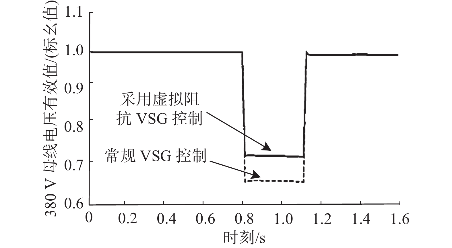
      为了验证本文所提基于虚拟阻抗的储能微网VSG控制策略可以有效提高当外送线路侧短路时候的LVRT能力,本文设置仿真工况为0.8 s线路发生对称短路(三相接地)、不对称短路(单相接地),1.16 s继电保护动作切除故障。采用常规VSG控制和虚拟阻抗VSG控制对比波形如图8图9所示。

      Figure 8.  Symmetrical short-circuit voltage waveform comparison of energy storage microgrid

      Figure 9.  Asymmetrical short-circuit voltage waveform comparison of energy storage microgrid

      根据图8可知:当0.8 s线路发生对称短路,常规VSG控制和虚拟阻抗VSG控制都可以响应电压暂态下降,在0.8~1.16 s之间,虚拟阻抗VSG控制因为虚拟阻抗电压提升明显,可以有效提高储能微网PCS输出电压,起到LVRT期间电压暂态支撑作用,相较于传统VSG控制,储能微网PCS输出电压提升0.12 p.u.,避免了对电压下降敏感用电设备低电压保护动作,使储能微网具备LVRT能力。

      根据图9可知:当0.8 s线路发生不对称短路,相较于对称短路,母线电压下降较少,常规VSG控制和虚拟阻抗VSG控制都可以响应电压暂态下降,在0.8~1.16 s之间,虚拟阻抗VSG控制暂态电压相较于传统VSG控制提升0.06 p.u.,1.16 s继电保护动作切除故障后,也可迅速恢复至额定电压,采用虚拟阻抗的VSG控制系统具备LVRT能力。

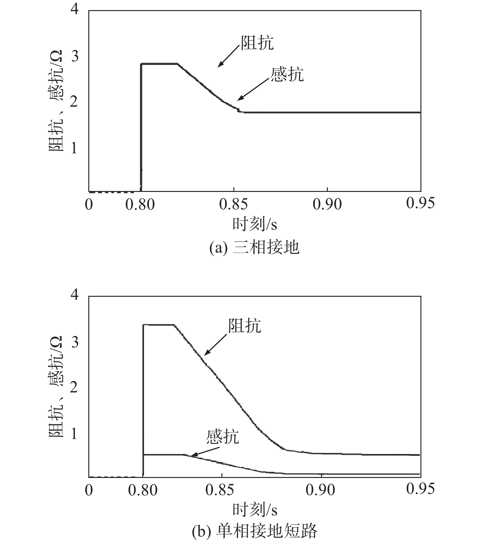
      图10为0.8 s时刻,线路发生三相接地、单相接地故障时,虚拟阻抗介入后,虚拟阻抗的阻抗、感抗变化情况对比图。

      Figure 10.  Simulation waveform diagram for virtual impedance change

      图10(a)可以看出:当发生三相接地故障时,虚拟阻抗介入后呈线性递减状态,此时虚拟阻抗阻感比始终保持在1,虚拟电阻与虚拟电抗幅值始终保持相等且始终与目标电压相匹配,起到电压支撑的作用。从图10(b)可以看出:当发生单相接地短路故障时,控制系统动态调节虚拟阻抗,虚拟阻抗阻感比与线路阻抗阻感比相同,并呈线性递减,起到最大支撑故障电压作用。

    • 本文提出一种储能微网PCS采用VSG控制策略。针对传统VSG不具备LVRT能力,引入虚拟阻抗到VSG无功-电压控制中。将LVRT工况分为网侧对称和不对称短路故障,为了得到虚拟阻抗的幅值及阻感比,将LVRT工况分为线路对称和不对称短路障,研究正、负序电压、电流,最终得到虚拟阻抗的虚拟阻抗幅值及阻感比。

      通过Matlab/Simulink仿真果表明:本文将虚拟阻抗引入VSG控制系统中,可以提高短路情况下储能微网PCS输出电压,起到LVRT期间电压暂态支撑作用,使储能微网VSG控制系统具备LVRT能力。具有一定的工程应用价值。

Reference (15)

Catalog

    /

    DownLoad:  Full-Size Img  PowerPoint
    Return
    Return